NSX NA1 How to Replace ABS Part 2 (Harness Edition)
- 2021.07.09
- Fiddling
- ABS, ALB, Anti Lock Brake, Antilock Braking System, Harness, Honda, NA1, NSX, Replacement
This article is a continuation of the article on replacing ABS Part 1 (Unit Edition).
For this ABS replacement, the modulators of other models were diverted. Harness kits are sold by various shops if it is a modulator for the latter model of NSX, and I think that there is almost no trouble with coupler on, but of course this can not be used as it is because the wiring is different. Harness kits are also quite expensive, and considering the time and effort of using them to replace wiring, I decided to make all of them.
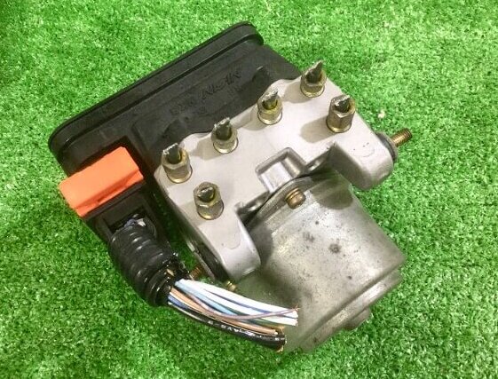
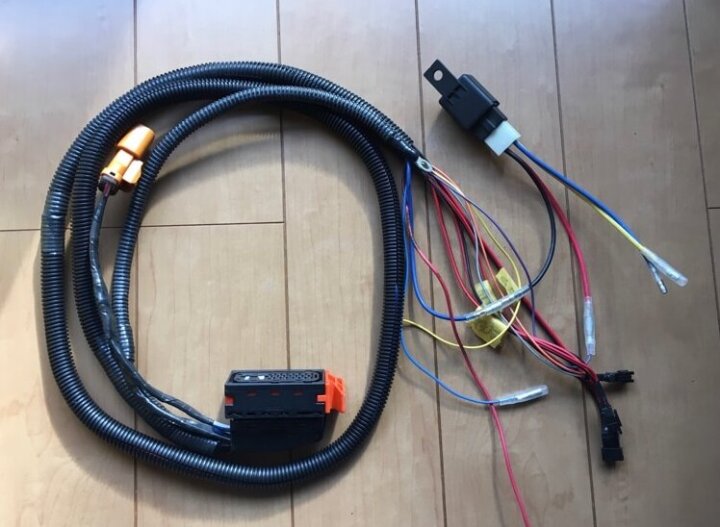
Therefore, one point is that when you buy a second-hand modulator of another model, you should buy not only the main body but also the one with the wiring cut in the middle as shown in this image. If it is only the main body, it will be necessary to obtain a coupler separately, and the hurdle will rise at once. If it’s just the main body, it’s rolling at a price like free.
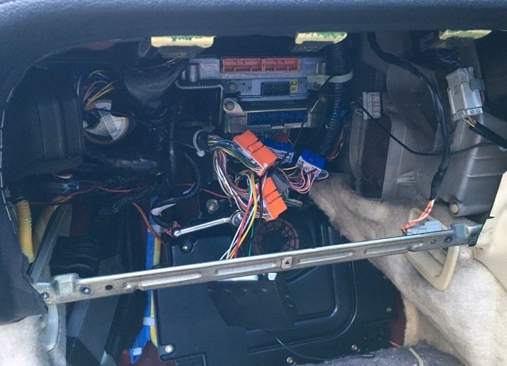
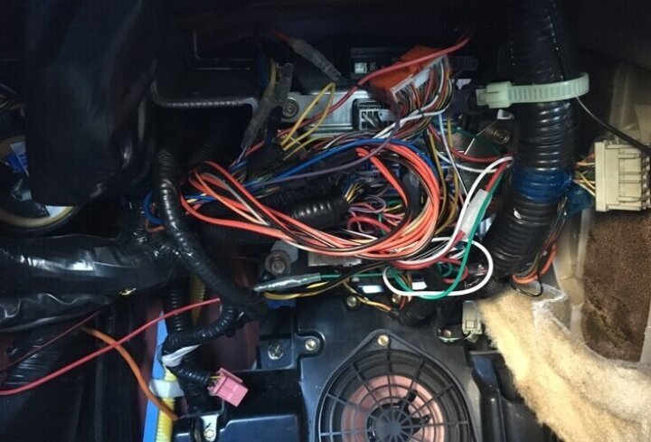
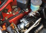
Access the ALB control unit by removing the glove box, air conditioning duct, and floor panel on the passenger side. I will remove this because it is no longer needed, but since it cannot be removed by itself, other control units must be removed at once. All you have to do is remove the visible bolts, but it’s a little difficult in a small space. Even when removing the main body, the stay at the bottom of the glove box is an obstacle.
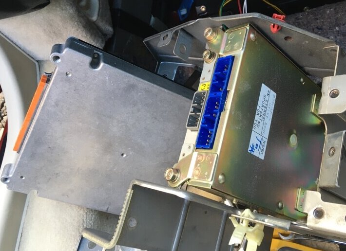
Finally the control units have come off.

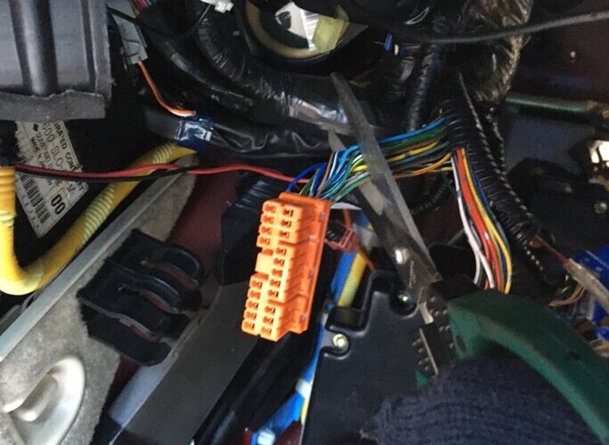
There are two types of orange couplers connected to the ALB control unit, 20 pins are ALB related harnesses and 18 pins are TCS related harnesses. I could have purchased the male side separately and turned on the coupler, but I will not return to ALB anymore, and it is impossible to use a large coupler when passing the wiring through the bulkhead, so it is necessary to relay with a small coupler. I broke the wiring cleanly. Then attach a small coupler to the cut end.
As an aside, when receiving a refresh plan, late ABS is not possible, so you will be returning to ALB. However, in that case, just attach a small coupler to the wiring on the coupler side where it was cut, and the coupler can be turned on again, so there is no problem.
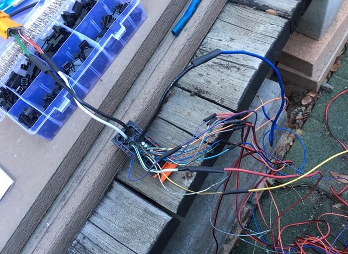
It looks like the harness is being made. I was likely to get complaints about soldering in my house, so I soldered it in the cold (2 ℃).
Harness completed.
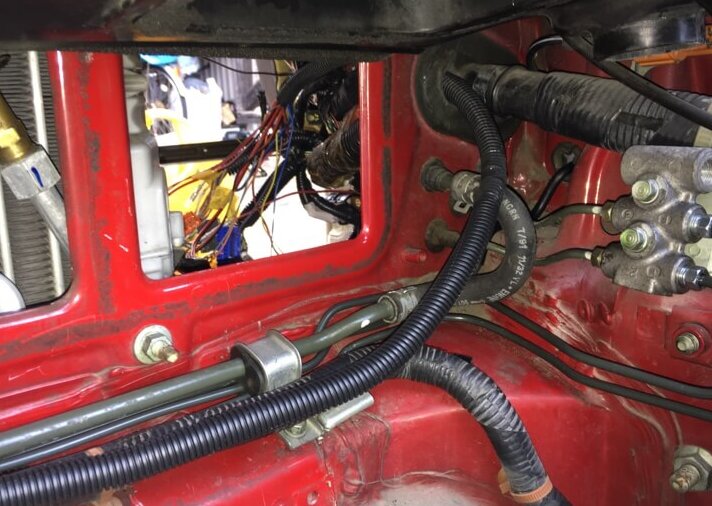
Pass the completed harness through the grommet of the main harness into the car. This photo is taken through temporary wiring. At first, I didn’t know the right wiring length, so I made each wire a little longer, 2m. And if I put it through, it was a little long, so I cut it down by about 30 cm. So if you make your own harness, I think that 1.7m is a guide, so please refer to it.
It’s cluttered and hard to see, but put back the control units that you removed once. The holes in the stay and the bolt holes on the car body side did not match easily, so it was difficult to fix it. Then connect it to the harness on the vehicle side. After that, return the blower fan, battery, and glove box around the car to finish the work.
Immediately for a test run to a nearby test course. It feels like the air is still biting a little, but there is no particular problem with the braking force. Even with full braking, the tires squeak intermittently, and there is no problem with ABS operation.
It’s done.
- Previous Posts
NSX NA1 How to Replace ABS Part 1 (Unit Edition) 2021.07.03
- Next Post
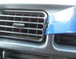
Suzuki Jimny Adjusting the Looseness of the Air Conditioner Louver 2021.07.11